
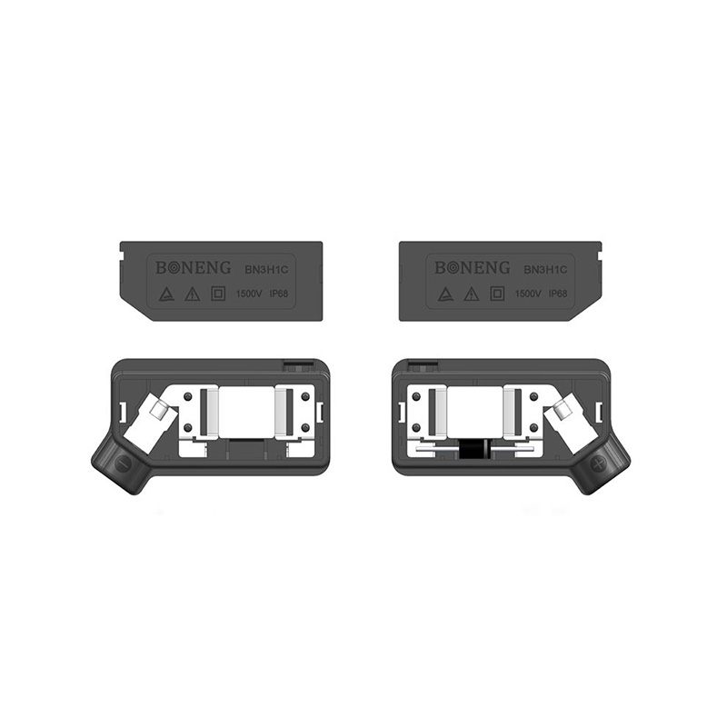
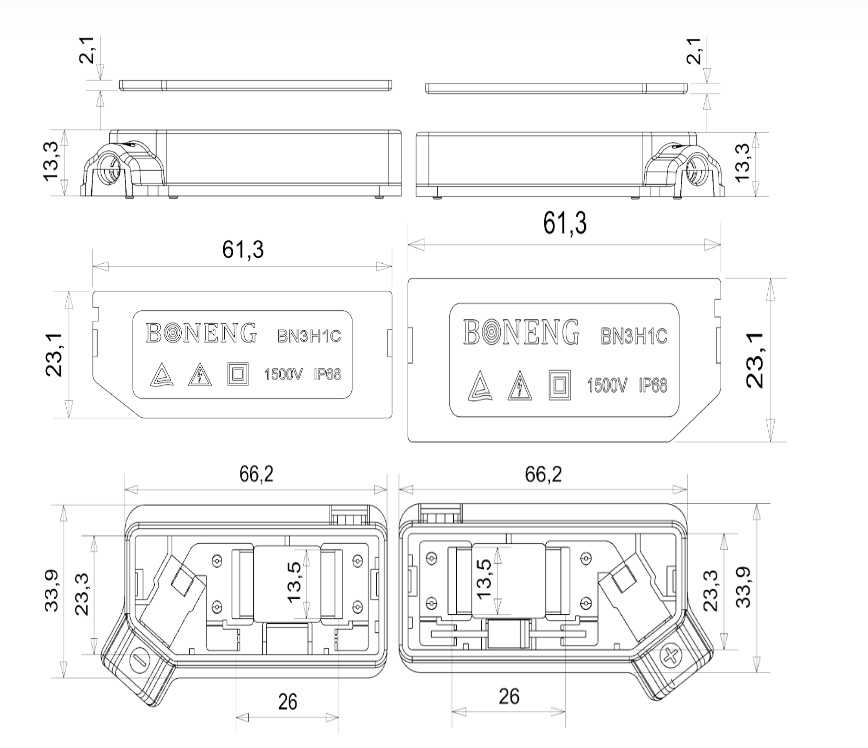
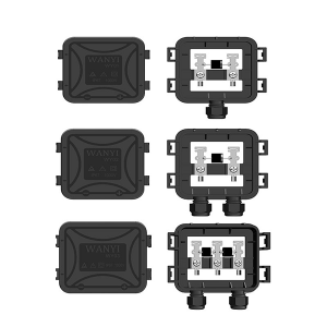
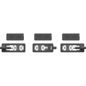
Full potting IP68 waterproof thin film junction box PV-BN3H1C
Technical Support
| MAXIMUM RATING (TA = 25 ℃ unless otherwise noted)(TA = 25 ℃, ) | |||
| PARAMETER | SYMBOL | 15SQ045 | UNIT |
| Maximum repetitive peak reverse voltage
|
VRRM | 45 | V |
| Maximum RMS voltage
|
VRMS | 31.5 | V |
| Maximum DC blocking voltage
|
VDC | 45 | V |
| Maximum average forward rectified current
|
IF(AV) | 15.0 | A |
| Peak forward surge cuurent 8.3ms single half sine_wave superimposed on rated load
@ 60Hz |
IFSM | 350 | A |
| Operating junction temperature range
|
TJ | -55 to +200 | ℃ |
| Storge temperature range
|
TSTG | -55 to +200 | ℃ |
Product Configuration List
| Diode Rated Voltage | 10A |
| Diode Type | 10A10 |
| Diode Qty | 1-2 |

Application
Unshielded solar panels for thin film batteries to improve solar energy
Solution
● PV module’s ribbon alignment must be complied with JB’s mounting hole of the terminal base.
● Adhesive and sealing compound, Potting glue must be applied by using specific type and specification. Make sure JB will be fixed in the correct position and reliable sealant. The potting glue level should be over the top surface of Diodes and terminal base. In order to avoid electrical shock risk.
● Don’t move PV module or JB before adhesive and sealing compound or potting glue solidify.
● Ensure soldering between Ribbons and terminal reliably in order to avoid missing soldering or false soldering. The soldering operators must be professionally trained. More soldering time will cause the diodes damaged.
● Adopt anti-static protection solutions when touch or solder JB.
● Make sure the connection method between JB and PV module in the correct polarity. Otherwise, Wrong connection will cause fire.
● PV module manufacturer should inspect the diodes of JBs before shipment since the diodes might be damaged by heat temperature or the static shock.
● Installation or maintenance should be operated by the professional personnel.
● For protection against electric shock, while being assembled or disassembled, make sure connectors isolated from the power supply.
● Don’t connected or disconnected under load.
● During the assembly process, keep the connector away from any corrosive materials.
Installation Instruction
1.Get a junction box and its base by a clean soft cloth with alcohol.
2.Panel back-sheet Upon, dry, no oil and other dirty. Clean the back-sheet area by a
clean soft cloth with alcohol.
3.Stroke straight the rubber by a pincers,keep vertical against the back-sheet.
4.Get a bottle silicon, cut the mouth of the bottle, making sure the diameter is 4mm, insert it into the air gun, screw cover, no cut on mouth of the air gun.
5.Put the junction box on working desk, get the air gun and keep vertical against the junction box base, gluing around the junction box base edge circle.
6.Get the rubber through the junction box base hole, press hardly the junction box on the back-sheet till the silicon overflow around.
7.Place panels across in the air currents 10 hours till the silicon cures.
8.Check the reliability of each terminal connection, and press the raised bus bar on the connection terminal by hand.
9.Cover the junction box with a click sound, the should not be pick out by hands.
FAQ
1) Are you a factory or trading company?
We have our own factories.
2) What is your FOB port?
FOB Shanghai, and we can according to customer requirements.
3) What is your delivery time?
3-7 days for samples, 10-30 days for large quantities, according to your order.
4) How about your after-sale service?
We can offer you timely and best after-sales service. Now we have built our relationship in many overseas countries like Brazil, Pakistan, Japan and German. It makes our after-sale service very easy and effective to reach you. Also our 24 hours online inquiry service is available.
5) Can I have my own logo on your products?
Yes, OEM&ODM service is available.
6) How to guarantee the quality of your products?
Our products have U L, TUV, IEC, RoHs, SGS and other certifications.
Vedio
Products categories
-

Small power solar panel crystal silicon junctio...
-

Full potting 1500V good quality split junction ...
-
High quality and hot sale pre-potting crystal s...
-
Split JB type PV-BN3H1T 1500V for crystal silic...
-
Hot sale small panel junction box PV-WY01、PV-W...
-
Competitive price 1500V good quality split junc...